In brief:
Some aspects of the Foucault Pendulum which I have not(yet) understood, for which I have not(yet) found a satisfying explanation, for which different sources in the literature give different or sometimes conflicting opinions.
Also, in my data processing I have room for improvement on the subject of extracting the ellipse parameters (major axis, minor axis, angle of major axis and rotational direction) from the available data.
I present the problems in the form of study tasks.
The biggest problem with Foucault pendulums is the tendency to develop an elliptical path which disturbs the Foucault Precession (FP).
This tendency has nothing to do with the earth's rotation, it would also happen on a stationary planet or on the eart's equator where the FP is absent.
Many publications about ellipse suppression methods exist, but few, if any, report convincing success.
The exception is the Charron Ring, which principle is almost universally used in permanently running pendulums.
Another rather well working option is a thick ring of electrically conductive metal, preferably copper, where a magnet in the bob hovers across near the end of the swing.
Study task:
Explain / derive why an elliptical path develops even in a pendulum on a stationary planet.
Explain / derive why the ellipse problem is more serious in short than in long pendulums.
Or does it only depend on the ratio of length and amplitude?.
Does the Q, the (inverse) amount of energy loss per period, has anything to do with the ellipse forming?
Describe the mechanism which transfers energy from the major axis to the minor axis and so produces ellipse growth.
Describe the mechanism(s) which limit ellips growth (I do NOT mean the Charron ring or eddy current damping)
Describe the mechanism which causes the ellipse to periodically change direction, and why this happens on the N-S and E-W transitions of the foucault plane. Would this also happen if the pendulum was located on one of the poles / on the equator / on a non rotating planet?
Schumacher derives that when a repelling impulse is given at a certain moment in each pendulum's half period that the precession of the ellipse (not the ellipse itself) will be perfectly suppressed.
Study task:
- Check the derivation of Schumacher, make a description of all steps-in-between, such that a less matematically trained person also can follow it.
- Check that the neglections which S. applies are justifyable and acceptable, c.q. reason what the remaining disturbations will be.
- Predict what happens if the impulse is to early or to late, or to strong or to weak, in terms of the FP regularity and total FP time. (per dec 2024 a series of tests have been done)
- Investigate whether the "Schumacher Drive" as I call it also limits ellipse growth.
- In my spreadsheet (download) is a section for the Schumacher calculation where manual iteration should be done. Try to automate that iteration process, or better, make it superfluous by making a direct derivation for the correct drive time.
Note: My experiments so far confirm the Schumacher criterium. Obeying the condition I find that the Foucault Precession is reasonably regular although there is a substantial ellipse which periodically changes direction.
Fitting a dataset to an ellipse.
In my dataprocessing I use a rather rude method to derive the ellips parameters (major axis, minor axis, angle of major axis and rotational direction) from a set of co-ordinate pairs. See the page about the PC-program.
There may be a beter way. Something like the least squares fitting of a straigth line through a number of (X,Y) coordinate pairs.
Study task:
Produce an algorithm, preferably written in C or Pascal and not using intricate math library functions that:
Given a array of co-ordinate pairs (x, y), laying on the perimeter of an ellipse with some small measurement errors, calculates the major axis, the minor axis, the angle of the major axis w.r.t. the horizontal and the direction in which the elliptical path goes.
The major axis of the ellipse can have any direction 0 .. 2*pi (or -pi .. + pi). Angles > pi are not distinguishable from angles < -pi. The minor axis will never be as long as the major axis (circle). The data in the array always start near the center, immediately after a centerpass has been detected, and the data pairs are in the order of the Bob's path.
The period of the pendulum's swing is known to a great accuracy as are the times on which the data pairs were sampled.
The "Fourier" or " Qadrature" method:
As I know the period of the pendulum T and the times of the Hall position measurements rather accurately I can make the following calculations:
for each whole swing do
for each Hall position measurement on time t do
- calculate sin (ϖ t/T) and cos (ϖ t/T)
- multiply and sum the X and Y positions into SumSinX, SumCosX, SumSinY and SumCosY
calculate AmplitudeX, AmplitudeY, PhaseX and PhaseY
N.b. The exact code for this calculation is at the end in the module u_calc.pas of the GUI software.
Currently these calculations are made and the results are logged by the PC-program, see below.
I have been able to reconstruct the ellipse from these data by X-Y plotting sine waves with these amplitudes and phases.
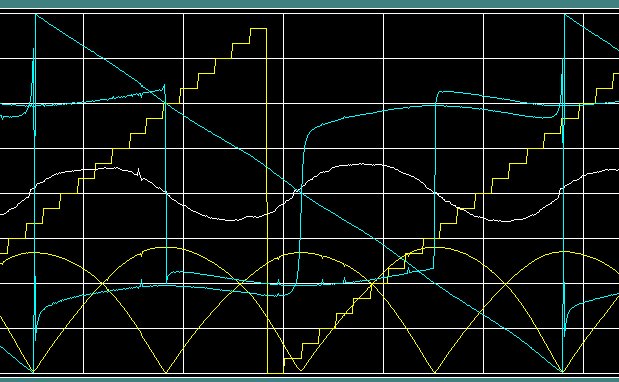
Fig 1. Output of the analyse program.
We see slightly more than one full period of the foucault precession (cyan sawtooth like function)
Yellow staircase: time of the day in hour steps, 00:00 .. 23:00.
White, centered: length and rotational direction of the minor axis of the ellipse. (The major axis is kept on a constant amplitude)
Yellow, at the bottom: Y- and X amplitude as calculated by the "fourier" algorithm. scale: arbitrary.
Cyan, centered: the Y- and X angles as calculated by the "fourier" algorithm. scale: +180 .. - 180 deg.
Study task:
Derive the ratio Minor / Major axis and the angle of the major axis from these data.
I know that the rotational direction of the ellipse cannot be recontructed this way.
Crane recommends both attracting and repelling drive with the argument that it would eliminate effects of certain asymmetries in the setup. However he hardly explains which asymmetries these are.
Note that Schumacher has some comment on this.
Study task:
- Give a mathematical derivation that the story about the center magnet is correct / incorrect.
- Indicate what happens when the magnet is to weak / far off or to strong / close by
- Indicate / derive which asymmetries can be suppressed by the combination of attracting and repelling drive and indicate what happens if the attracting and repelling impulses are not equal.
Permanent magnet in the center:
Crane recommends a repelling magnet in the center to eliminate the precession of the elipse,
Intuitively it feels that an attracting magnet in the center will reduce the amount of ellipse. After all, when the Bob passes straight over it will not have a net effect, because the effect of the attracting force will be cancelled by that of the repelling force after the pass. However, if there is an ellipse, there will always be an attracting force towards the center.
The contra is: If it is so simple, why is it not done always?
Study task:
- Explain whether or not a permanent magnet in the center of the base unit will reduce the ellipticity. The Bob does have a permanent magnet in the lowest central position.
- Explain what will happen when the magnet is to strong or to weak or is not very precise in the center.
Szostak recommends a repelling drive to counteract the forming of an ellipse. T.m.h.o. his figure 3 indicates just the opposite (Or I do not understand it)
Study task:
- Explain that Sz is right / wrong with his argument in favour of repelling drive.
Make the pendulum swing time independent of the amplitude.
It is known that the period time of a pendulum depends slightly on the amplitude, even for very small amplitudes.This may have certain consequences.
See the page PeriodTime.
What if we are able to make T independent of a ?
This picture demonstrates that a pendulum with the wire locked between two cycloids has a period independent of the amplitude.
The length of the pendulum must be such that the bob touches the cycloid exactly in the middle.
The question is: If we make the swing time of our pendulum independent of the amplitude, will the ellipse precession disapear?
The Huygens trick can be applied by using a properly shaped tube around the pivoting point (kind of trumpet shape).
The contra is that the formula for the ellipse precession tells me that the precession increases with a larger minor-axis. This is contray to the thought where the difference between the minor- and major axis' swingtimes is responsible for the precession. In that case we should see less precession when the swingtimes are closer to each other.
Study task:
Pull me out of this swamp.
Pivotting point not well defined.
In my setup there is no well defined pivotting point; the pendulum wire with a finite thickness is mounted in a minature type of drill clamp which is fixed to the structure of my house. The swinging of the pendulum bends the wire slightly making the exact pivotting point go slightly up and down during the swing.
Also bending the wire produces some sideway force on the wire.
Study task:
Given the parameters of the pendulum make an estimate of the way the effective pivotting point moves during the swing, and what the effects might be.
The parameters are: L= 4202 mm, a= 230mm, Bob weight = 5.858 kg, wire thickness 1 mm round, elasticity modulus 210 N/mm².
The wire is operated within the range of forces where only pure elastic stretching occurs.
Anisotropy in the system:
At many locations an anisotropic situation will exist. Maybe small but certainly not zero. Some known or very likely abberations are:
- The magnet in the bob (or its field) does not sit perfectly in line with the suspension wire and the center-of-mass. This can be seen when the bob is rotating along its own axis. Such a rotation generally occurs when te bob is launched by hand. We can then see that the center-pass time varies slightly with a period of some tens of seconds. Eventually this rotation dies out.
- The drive coil is not perfectly centered w.r.t. the centerpas detection coil. The centerpass coil is rather well centered during the center-adjust procedure, but the drive coil will have some deviation. Also these coils are "wild" wound which may lead to a non-coaxial magnetic field.
- The Rim coil might not be perfectly symmetric around the center- and drive coils.
- The plane in wich the coils lay might not be exacly horizontal.
- The bob has a rather strong magnet and will be influenced by the earth's magnetic field. Also the magnet in the top mount experiences this field. (The experiments with magnetic fields demonstrated that these efects are quite small)
- Some 30 cm below the coil plane are iron rods as reinforcement in the concrete floor of my living.
- Crosswind: on the Results page I report that even an almost unnoticeble crosswind has an enormous influence. Use a candle to test air draugth.
Study task:
Give estimations for the effect of these asymmetries.
Give suggestions for practical tests and think about this: If you suspect an effect from some influence and the influence is hard to eliminate, then make the influence worse and see what happens. I did that with the crosswind experiments and the magnetic fields..