In brief:
The most remarkable finding is the periodic change in rotational direction of the elliptical path, the fact that these changes seem to take place at the N-S and E-W transitions, and that they restore quite fast when kicked into the other direction.
I did a series of experiments to shine more light on what the causes of the several phenomena might be.
Fig 1. Animaton of screenshots form the compass display, taken at intervals of 5 minutes and covering one complete Foucaut rotation.
The display is aligned with the compass directions at my location
We see a number of position measurements from the Hall detector system.
Light-blue: HalfPeriod-1, white: HalfPeriod-2, Red circle FP plane orientation.
Green blip: first sample after a CenterPass, red blip: Green blip, after rotation to horizontal laying ellipse.
The rotational direction of the ellipse is from the green blip into the light-blue blips.
So we have CW direction in quadrants 1 and 3, and CCW in quadrants 2 and 4.
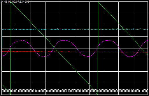
Fig 2. Time display on the GUI. Vertical scale 45 px / div
Green: Precession angle, 5 hours / div. +180 .. - 180 deg. Center = E-W.
Purple: Ellipse minor axis, 5 hours / div, 45 mm / div. + = CCW, - = CW.
Others at timescale of 1 pixel per half-period: 50 px / div.
White: indication of drive pulse minimum or maximum.
Red: amplitude of signal from center pass coil.
Light blue: pendulum amplitude (kept constant at 230 mm).
Graph runs from 2024-07-30_07:00 to 2024-08-01_09:07.
The ellipse changes direction at precisely the N-S and E-W transitions.
Zero crossing intervals of FP:
07-30_09:59 to 07-31_01:04 giving 15:05 for half FP
07-31_01:04 to 07-31_15:50 giving 14:46 full FP = 29:51.
07-31_15:50 to 08-01_06:43 giving 14:53 full FP = 29:39.
08-01_06:43 to 08-01_21:43 giving 15:00 full FP = 29:53.
The theoretical full FP is 30.4 hr for my lattitude (NL).
Data source: 2024-07-30.log to 2024-08-01.log.
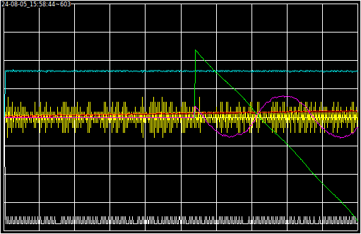
Fig 3.
Like fig 2, but including the difference in time between the halfswings (yellow)
Scale: Vert: 45 usec / div. Hor: 50 px / div, 1 px = 1 halfswing.
This yellow display is primarily used to center the coilset on the floor unit.
Scale is 0.035 mm / px or ca 1.6 mm / div.
(system was restarted some 23 hours before this screenshot.)
Experiment about misalignment of bob's magnet. (2024-08-18)
The magnet in the bob consists of a pile of 4 strong neodymium magnets of 10 mm diameter and 5 mm thick, They fit with little play in a borehole in the lower stem. Also the iron M6 coupling rod influences the shape of the magnetic field. (see bob drawings, fig 2 and 3)
I know that the magnetic field is not perfectly aligned witht the bob's axis.
This morning I did a new test to estimate the amount of asymmetry.
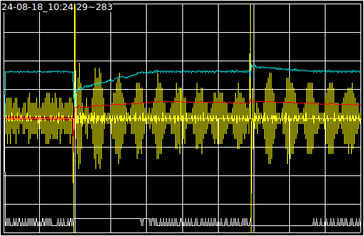
Fig 3. Bob relaunched with rotational effect.
Display:
The horizontal time scale is 1 pixel per halfswing or ca. 100 sec per div.
The vertical scale is 45pixels or units per div.
The yellow trace is the difference between the centerpass times of successive halfswings in 10 kHz ticks / pixel or 4.5 ms / div.
The bob's velocity in the center is 0.35 m /sec (see Spreadsheet) so the scale is 1.6 mm / div.
The experiment:
The left 2 divisions give the situation before the test started, the bob had no axial rotation.
On division 2 I took the bob in my hands, rotated it CW over slightly more than 180 deg. and let it go.
We see the time difference grow and shrink with a period of ca. 35 halfswings or 70 seconds due to the bob's action as a torsion pendulum.
We see the amplitude (as calculated from the Rim coil passage time, light blue) grow to 230 mm, then the stabilisation mechanism starts switching the drive pulses between minimal and maximal duration. (white trace at the bottom)
The red trace is the peak signal from the Center coil. Before the test there was an amount of ellipticity, so that signal was lower. Relaunching the bob has set the ellipticity to almost zero, so we have more signal from the center coil.
At division 7 I repeated the test, this time I relaunched the bob with a slightly to large amplitude. The amplitude trace now shows shrinking until the stabilisation mechanism catches up.
Conclusion: the misalignment is in the order of 2 mm, but it is calibrated away by the centering procedure of the coilset. This is for the sake of center detection only. There may very well be a remaining effect for the Drive coil and for the Rim coil.
I'm thinking about a method te reduce this misalignment.
I have plans to:
- build a short, relocatable pendulum with a drive method that excites the frequency of the major axis, and not the slightly higher frequency of a minor axis, thus suppressing ellipse growth.
- experiment with a cycloidal suspension in an attempt to make the swing period (more) independent of the amplitude.