in brief: In a free hanging pendulum following an ellipticat path the movement consists of two perpendicular,
almost sine-shaped components with a different period time. In the literature about the Foucault pendulum this aspect is mostly disregarded or not even noticed.
At a closer look this effect appears -at least for shorter pendulums- to be far from small.
The Period time.
For the calculation of the period time we mostly use the well known formula: [1]
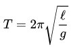
where L is the effective length of the pendulum and g the acceleration of gravity, around 9.81 m / s2.
This formula however is an approximation because in the derivation it is stated that for a small angle sin (Θ) = Θ,
which is not correct. The deviance is small, however not zero.
The formula for the exact swing time is: [2]
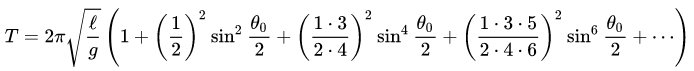
where Θ0 = arcsin (a/L).
In the table below we see the contribution of the first 4 terms after the + sign as function of the maximum angle, expressed as a/L in %.
| % a/L | Term 1 |
Term 2 |
Term 3 |
Term 4 |
| 0.1 |
0.000000062500015625 | 0.000000000000008789 | 0 (*) | 0 (*) |
| 0.2 |
0.000000250000250001 | 0.000000000000140625, | 0 (*) | 0 (*) |
| 0.5 |
0.000001562509765747 | 0.000000000005493233 | 0.000000000000000024 | 0 (*) |
| 1 |
0.000006250156257813 | 0.000000000087895020 | 0.000000000000001526 | 0 (*) |
| 2 |
0.000025002500500125 | 0.000000001406531320 | 0.000000000000097686 | 0.000000000000000007 |
| 5 |
0.000156347778511382 | 0.00000005500041265 | 0.000000000023886645 | 0.000000000000011437 |
| 10 |
0.000626570361672506 | 0.000000883328440784 | 0.000000001537409502 | 0.000000000002950092 |
(*) within the precision of the computer. [4]
Elliptical Path.
In a pendulum following an ellptical path we can see the movement as consisting of two perpendicular, near sine-shaped components, the major and the minor axis. These components have slightly different period times. Supposed that the initial phase difference is 90°, in the course of time this difference will increase or decrease. The patterns produced this way are known as figures of Lissajous.
The table below shows after how many periods this phase shift reaches 360°, being back at the starting situation.
To find the time it takes for the full phase shift we have to multiply the number of periods by the pendulum swing time. Then we see that the effect is much stronger in a short pendulum and increases rapidly with the amplitude.
In the 4th column that time is given for a 4 meter = 4 second pendulum like mine.
Note: 4 meter = 4 seconds is an easy to remind approximation. But mind the squareroot.
Note: My pendulum has some 5% amplitude (white).
| % a/L | Correction | # periods for 360° | Hours @ 4 meter 4 sec pendulum |
| 0.1 | 1.000000062500024414 | 15999994 | 17777.8 |
| 0.2 | 1.000000250000390626 | 3999994 | 4444.4 |
| 0.5 | 1.000001562515259004 | 639994 | 711.1 |
| 1 |
1.000006250244154359 | 159994 | 177.8 |
| 2 |
1.000025003907129138 | 39994 | 44.4 |
| 5 |
1.000156402802822117 | 6394 | 7.1 |
| 10 |
1.000627455230472883 | 1594 | 1.8 |
Fig 1. Animation of the effect of a frequency difference between major an minor axis.
Red: Sine wave of major axis plotted against time.
Green: Sine wave of minir axis plotted against time.
Yellow: X-Y plot.
Blue: Rectangle surrounding the X-Y plot.
Note: This is not the behaviour of a foucault pndulum, it is just a simulation of two sine waves.
What can we do?
Well, in such cases one should consider “Can I eliminate / reduce the influence” or “Can I use it to my advantage”.
Traditionally foucault pendulums are made long and with a small a/L to reduce this and some other effects.
But we have an historical example where the 16th century scientist Christiaan Huygens suspended the pendulum of his clock between two curved brackets which effectively shortened the pendulum at increasing amplitude.
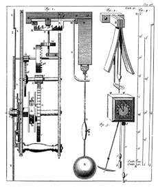
Fig 2. Huygens clock.
I do not know if he knew that the optimal shape of these brackets is a part of a cycloide.
And the cycloid has the nice property that with the proper length of the cable, the period time is independent of the amplitude.
Fig 3. Cycloidal Pendulum.
Can we apply this trick to our pendulum which must swing freely in all X-Y directions? I think so.
We should make a properly shaped “trumpet” to suspend the cable from.
The second thougth, make use of it, is essentially what I think that Pippard [3] and some others do: exiting the pendulum at the frequency of the major axis, while preventing to excite the slightly higher minor axis frequency.
For this to work well we should use a pendulum with a larger than usual amplitude, and a high Q, such that there is a good frequency difference. We also need a very stable and fine tunable frequency source.
For a high Q we should maximize the ratio mass / crossection of the bob and make the cross section more “airodynamic”.
The stable and fine tunable frequency can be made with modern Direct Digital Synthesizer devices like the AD9850 from Analog Devices.
Conclusions:
The plane in wich a practical Foucault pendulum swings is determined by
at least 3 effects, the Foucault precession due to the earth’s rotation,
the intrinsic precession of the elliptical path any pendulum will
eventually follow, and the above mentioned effect due to the different
period times of major and minor axis.
To my knowledge only Pippard [3] refers to the latter circumstance where
he tries to excite his pendulum at the period time of the major axis,
not the minor one, and so limits the amount of ellipticity.
Unfortunately my knowledge of math is far from sufficient to further elaborate all of this.
On
the other hand, there are possibilities to either reduce or make use of
the effect, particularly in short pendulums, and I plan to experiment
with both approaches.
References:
[1] and [2]
Source:
https://en.wikipedia.org/wiki/Pendulum_(mechanics)
[3] Pippard: “The parametrically maintainded Foucault pendulum and its perturbations”
and
Pippard: “The physics of Vibration”, chapter 10.
[4] The Free-Pascal code used for the exact period time:
procedure ExactTerms (AmplitudePercent: extended);// we use the formula given in:
// https://en.wikipedia.org/wiki/Pendulum_(mechanics)
// as the Legendre polynomial solution
var Theta, SinHalfTheta, Term1, Term2, Term3, Term4: extended;
begin
Theta:= arcsin (AmplitudePercent / 100); // angle at maximum position
SinHalfTheta:= sin (Theta / 2);
Term1:= sqr (1 / 2) * power (SinHalfTheta, 2);
Term2:= sqr (3 / 8) * power (SinHalfTheta, 4);
Term3:= sqr (15 / 48) * power (SinHalfTheta, 6);
Term4:= sqr (105 / 384) * power (SinHalfTheta, 8);
// show the contribution of each term
MemoAdd (format ('%22.20f, %22.20f, %22.20f, %22.20f',
[Term1, Term2, Term3, Term4]));
end;