The Position Measurement System (PMS) produces information about the actual position of the pendulum in the horizontal plane.
It consists of an arrangement of sensors and associated electronic circuits.
In an earlier pendulum I used an arrangement of a magnet and analogue Hall sensors for this purpose. In this pendulum I try to not use magnets, where possible.
The first attempt for a non magnet based PMS relied on cheap optical distance sensors of the type GP2Y0A51SK0F from Sharp. 2 pairs of sensors were placed opposite to each other in N-S and E-W direction. On the wire was a cylinder painted matt white. The signals from the sensors were treated much the same as in the earlier PMS with the Hall sensors. During the first test however it became clear that these sensors, although the output is analog, produce the signal in discrete steps of roughly 1.3 mm which I regarded unacceptable.
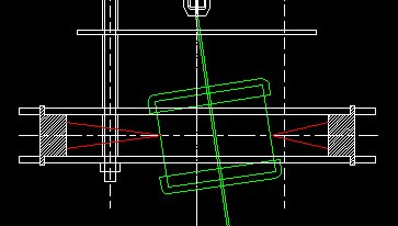
Fig 1. The rejected PMS with optical distance sensors.
Fig 2. Transfer characteristic of the optical sensors
Horizontal axis: Wire displacement from -120 to + 120 mm
Vertical axis: Output signal from two opposite sensors.
Then I came to the idea of using a capacitive method to measure the bob's position. It was already planned to use a capacitive method for detecting the bobs center and rim passes, and for that purpose the wire and bob should carry a 465 kHz AC signal. A proof of concept had shown already that it worked fine for center and rim detection. Why not use it for position sensing too?
A construction was made with 4 identical sensing electrodes and shielding electrodes which also carry the 4 receivers. The wire now has an aluminium cylinder of 20 mm diameter and 70 mm length, which moves between the electrodes. For the receivers a small PCB was made, located on the shielding electrodes.
The capacitive method produces signals in the mV range, and is sensitive to disturbing electric fields like mains hum and RFI. So shielding is required. Also the line between the sensing electrode and the (first stage of the) receiver must be short and must have a low capacity to GND.
All metal construction parts of the whole setup are connected to system GND.
The frequency of around 465 kHz was chosen because for that frequency cheap band pass filters are available, the type used in IF stages of AM radio receivers.
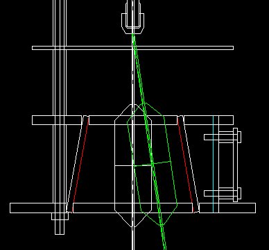
Fig 3. Construction drawing of the PMS.
Red: conductive side of sensing electrodes.
Cyan: conductive side of shielding electrode
Green: the wire and cylinder in the extreme position.
On the outside of the shielding electrodes sit the receiver PCB's.
Later on it turned out that the cylinder around the wire is not needed. It works as well with only the bare wire.
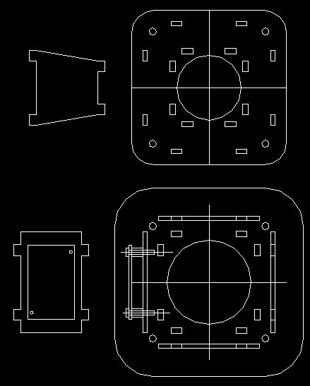
Fig 4. Most parts of the PMS were laser cut from 5 and 3 mm thick acrylic plate material.
Top left: 1 of the 4 sensing electrodes, right the top plate
Lower left: The shielding electrode with the receiver PCB, right the bottom plate.
The electrodes were made conductive with graphite spray. I used Cramolin Graphite, article nr 1281411, giving a surface resistance of a few kOhm. The electrical connections were made by strips of copper tape, applied before spraying.
Do not use "Anti Static" spray. The conductivity is much to low, 10's of MegaOhms.
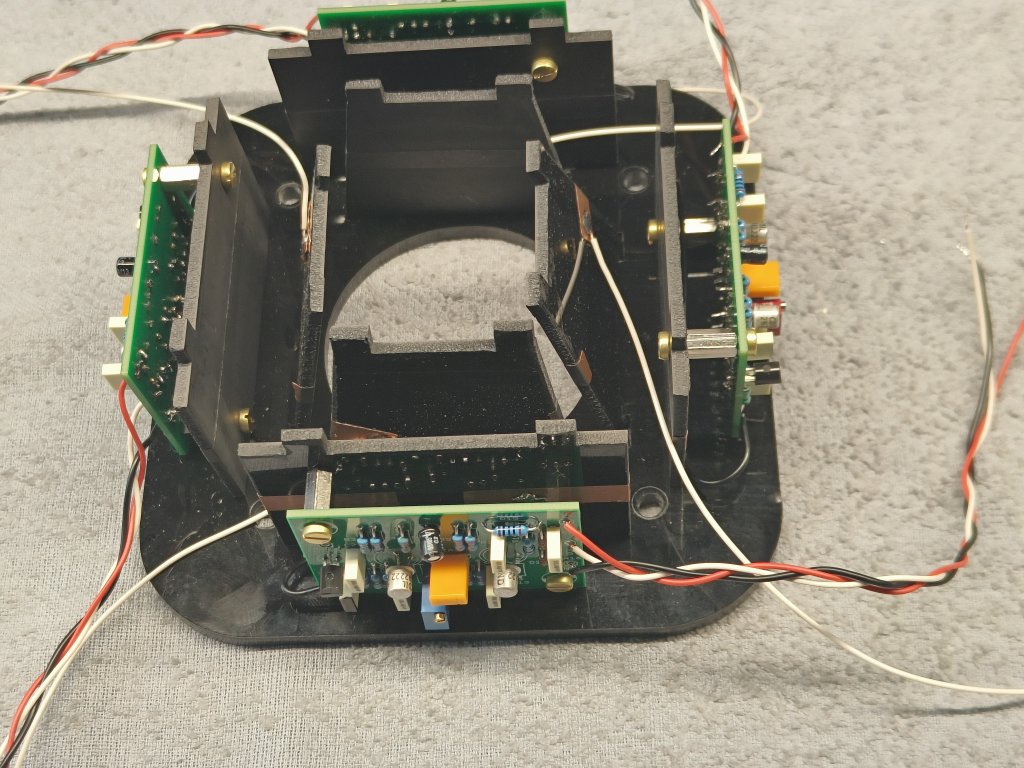
Fig 5. The PMS assembly, without the top plate. The long white wires are to connect the sensing plates with the receivers.

Fig 6. The receiver principle.
The signal source basically consists of the capacity between the wire carrying the 465 kHz signal and the electrode, and the capacity between the electrode and surrounding GND. So the received signal is quite small and we need a pre amplifier stage with high impedance and low capacity.
For the input stage I took a J-fet, the well known BF245C.
The second stage with Q2 has a variable gain, depending on the trimpotmeter R8.
The band pass filter is of a type meant for the IF stage of AM radio receivers. These filters typically have a bandwidth of a few kHz, so the exact frequency of the stimulus is not very important.
The third stage has a fixed gain to be set by R13.
The circuit with the diodes D1 and D2 rectifies the signal to a DC value that can be measured by the Arduino.
During further experiments it became clear that the solution with the graphite-painted electrodes was not very reliable, most likely due to uneven distribution of the graphite layer. It resulted in strange non-linearities in the position measurements.
Then I decided to implement the shielding and sensing electrodes in Printed Circuit Board technology, with low impedance copper layers.
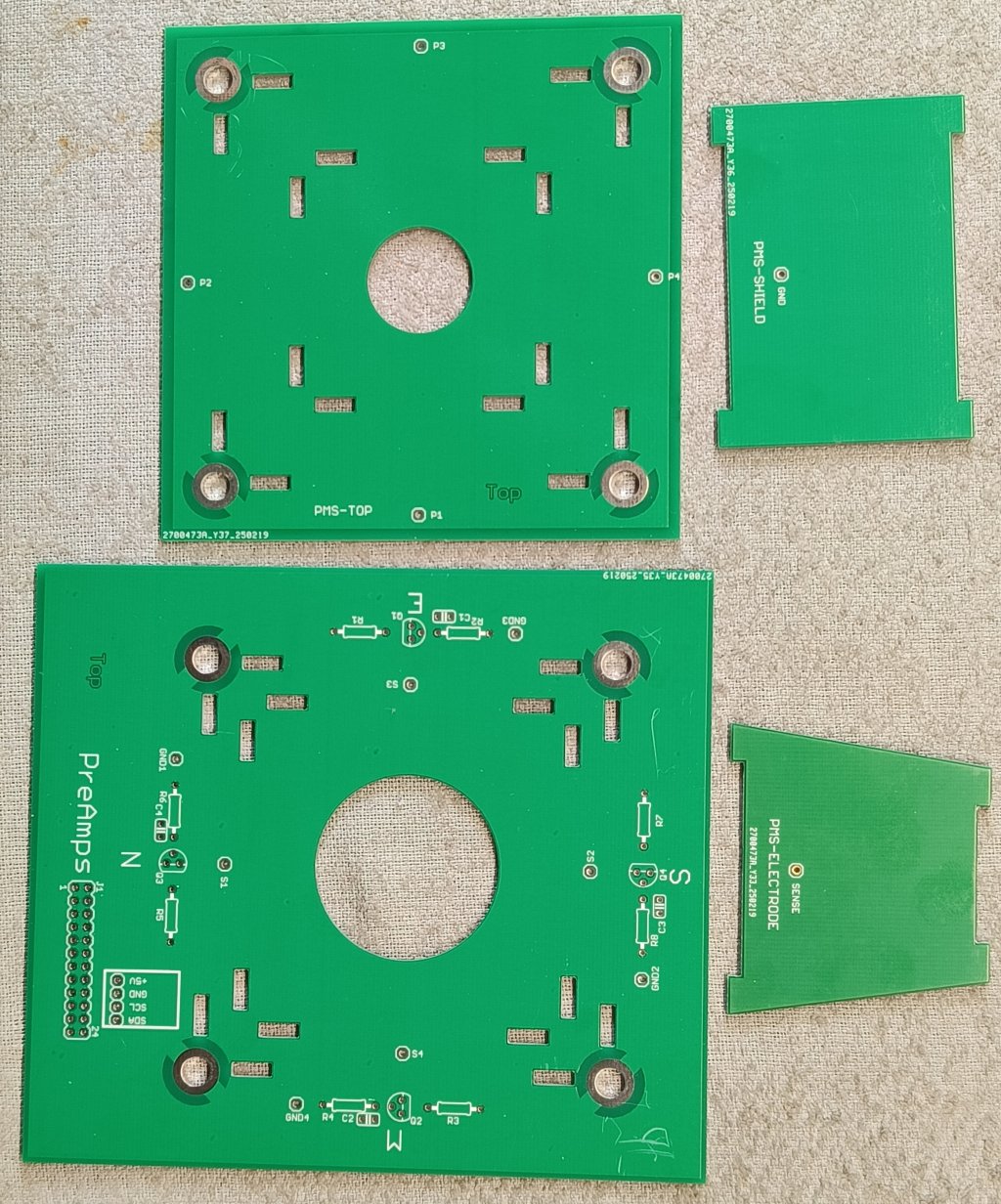
Fig 7. The bare Printed Circuit Boards of the PMS.
All boards are double sided and have a ground planes on both sides.
The bottom plate accomodates the J-FET pre-amplifier stages and a BME280 climate sensor.
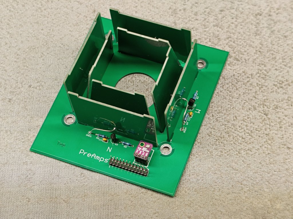
Fig 8. PMS without the top plate.
The circuit of the receivers was a bit changed too.
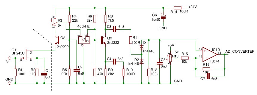
Fig 9. Pre-Amplifier and Receiver.
The left part with Q1 is on the PMS bottomplate.
Q1 and Q2 are in a cascode configuration. The advantage is that the input on the emittor of Q2 has a low impedance which causes the signal voltage to be very low there, and so prevents cross talk on the flat cable between the PMS and the receiver board.
The gain adjustment by R3 now has a linear characteristic, in stead of the 1/R characteristic when it controlled the amount of emitter decoupling. This makes adjustment much more easy.
The emitter of Q1 must not be completely decoupled. If the voltage gain of Q3 is to high it will result in a near-oscilating circuit with the inductive impedance of the ceramic filter and the parasitic capacitances.
After rectifying the signal with the diodes we have a possibility to compensate for the offset. It is to be seen if this is needed, up to now I have not used it.
The output signal goes to an analogue input of the Arduino MEGA,
The Receiver board has 6 of these circuits, 4 for the PMS, 1 for the CenterPass detection and 1 for the RimPass detection.
It may turn out that RimPass detection is not needed, because the width of the center detection pulse is inverse proportional with the velocity of the bob and so with the amplitude of the pendulum. I think that controlling the amplitude of the pendulun can be done this way.
See also: Calibration of the Position Measurement System.