For the calibration of the PMS I used the frame and steppers from a SculpFun S10 Laser Cutter.
Fig 1. SculpFun S10.
From this machine I removed the Laser Unit (and mounted it on my own built CNC machine).
The original electronics was replaced wit a subset of my CNC machine, for compatibility and some special features.
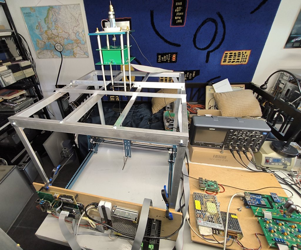
Fig 2. Setup for calibration of the PMS. (click for larger)
The TopUnit with the PMS is placed on top of the new frame.
The wire is attached to the carret of the Sculpfun by an insulating nylon rope and a spring to keep it on tension.
Lower left the special CNC electronics,
Right, part of the pendulum electronics, stil in an improvised stadium.
Fig 3. Center Disk. (click for larger)
The first step in calibrating the PMS is to make the gain of the 4 channels identical and half-scale while the wire is in the center position.
The wire can be centered precisely with a special disk which fits in the black plate, specially made for this.
For the calibration process I have 3 special g-code files,
One which makes a movement only in the X-direction, with Y = 0, and measuring steps each mm,
One which makes a movement only in the Y-direction, with X = 0, and measuring steps each mm,
One with measuring positions at a 20 mm grid in both X and Y, covering somewhat more than the intended amplitude of the bob.
My CNC software supports some special commands to measure and log the signals from the PMS.
The data from the first 2 measurements were processed in the spreadsheet program LibeOffice Calc.
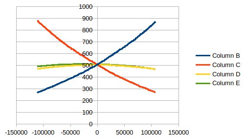
Fig 4. Processed data from the North-South scan. (Y-Y)
Blue North, Red: South, Yellow: East, green: West. Raw data from the PMS.
We see some non linearity when the wire comes closer to the detection electrodes.
We also see some 2nd order cross talk in the other channels, and some rotational error.
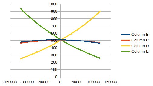
Fig 5. Processed data from the East-West scan. (X-X)
Blue North, Red: South, Yellow: East, green: West. Raw data from the PMS.
We see some non linearity when the wire comes closer to the detecion electrodes.
We also see some 2nd order cross talk in the other channels, and some rotational error.
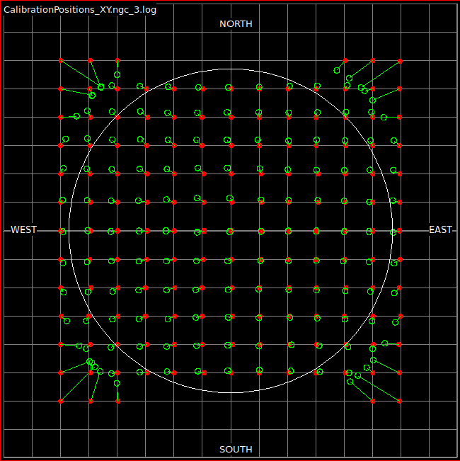
Fig 6. Error Map of the 2D scan produced by a specially written program.
Red dots: measuring positions, Green circles the result.
Circle: the intended maximal amplitude of the pendulum (scaled).
The signals from the PMS were first normalized as PosNS:= (N - S) / (N + S) and PosEW:= (E - W) / (E + W).
Further corrections for scaling, offset, rotation and quadratic cross talk can be made by sliders in the analysing program.
The parameters found with this program can then be entered into the Pendulum Control Program.
As can be seen there is room for improvement.
This was the situation in march 2025. Several improvements are planned.