A short video of the swinging Bob.
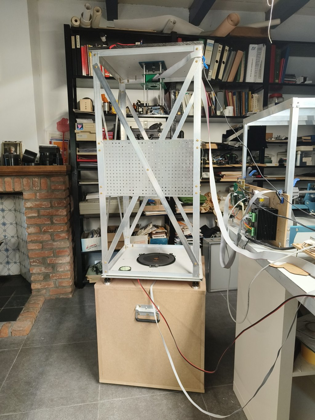
Fig 1. Frame on the base block. (click for larger)
The frame is constructed from Aluminium L-strips 30x30x2 mm, perforated plate and flat strips 25x2 mm.
The top and bottom plates are made of High Pressure Laminate (Trespa) plates of 13 mm thick.
The inside height is 1000 m, given by the standing L-profiles.
At first only the peforated plates were mounted to give the frame its rigidity, but soon after the bob was swinging it became clear that that was insufficient. So the reinforcing diagonal strips were mounted.
The unit is placed on 4 adjustable feet, which allow precise vertical aligning. The feet have locking nuts which must be fixed after adjustment, to prevent wobbling.
In the very first test phase the unit was standing on a table which appeared to wobble too. So a cubical base block was made from 18 mm thick Medium Density Fireboard (MDF) This block rests on 3 M8 capped nuts on the stone floor of my study.
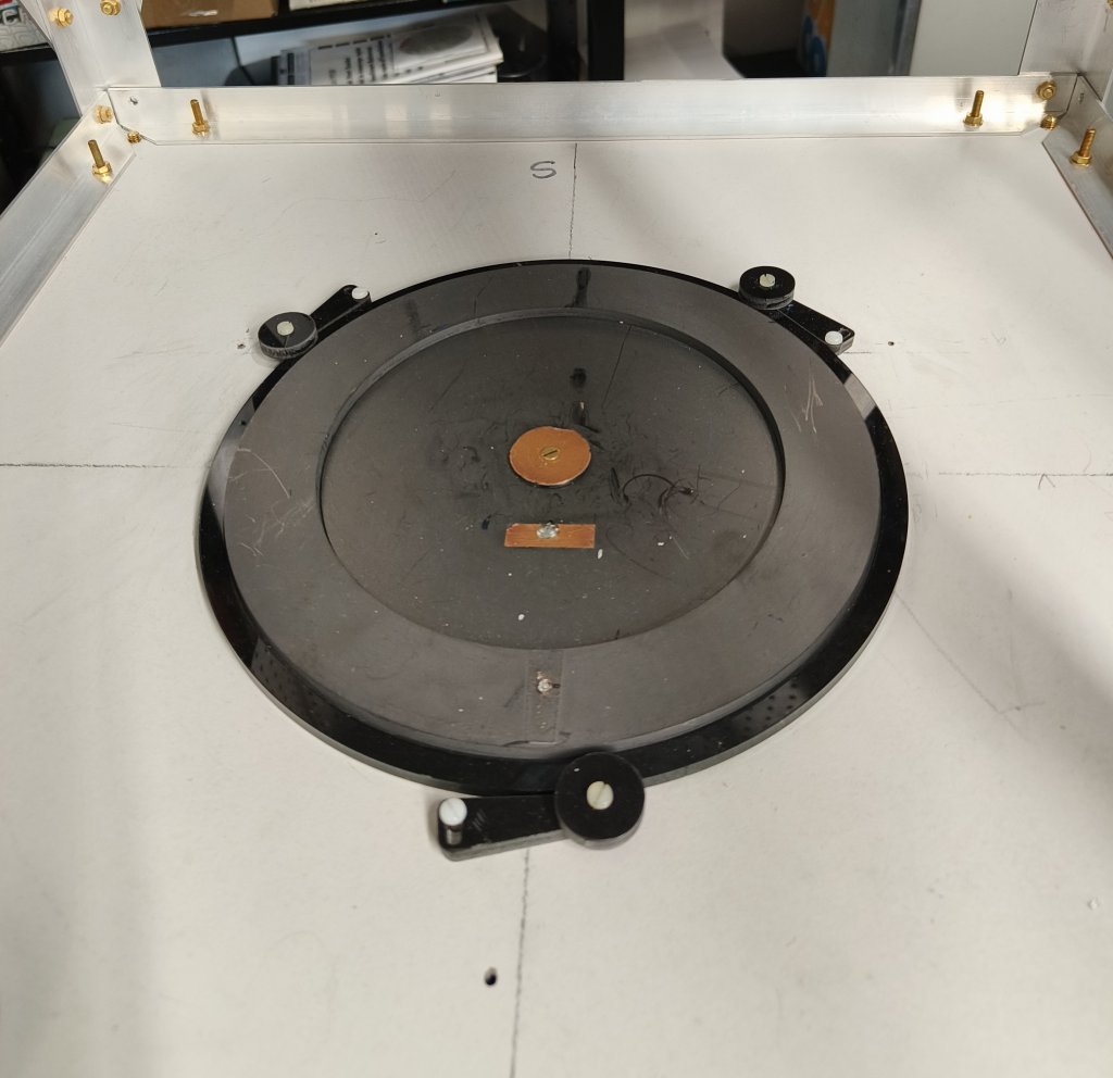
Fig 2.Floor unit with Center- and Rim sensing electrodes (click for larger)
The floor unit is stil made of graphite painted acrilic material.
Here we see the center electrode, a thin piece of copper foil, on top of the (invisible) drive coil.
We can also see the rim electrode, which probably will not be used.
The bottom side of the trespa bottom plate is covered with a copper foil connected to system GND, for EMI screening.
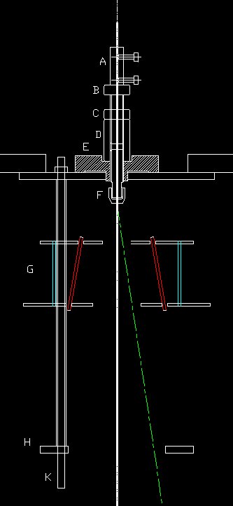
Fig 3. Top Mount.
The top mount is designed such that all the weight of the bob is taken by the brass cylinder A on the very top, and not by the Proxxon clamp F.
This allows the clamp to only prevent the wire from shifting in the horizontal plane, and no need for very strong clamping to prevent the wire slipping out.
I hope that this arangement will reduce the chance of a broken wire which initially happened a few times.
Other parts of the construction are:
B: a M10 hexagonal screw, centerdrilled to allow the wire pass. With this bolt the height of the bob can be fine adjusted.
C: a M10 nut to fix the screw after adjusting the height of the bob.
D: a M10 coupling nut (long nut) fix the carrier of the clamp. Also used to connect the 465 kHz signal.
E: a supporting part made from insulating material: POM or Delrin.
F: a clamp and cap from a Proxxon small drilling machine. A piece of M10 threaded rod was partly retreaded to accept this clamping cap.
G: the Position Measuring System described elsewhere.
H: Lower plate. Can accept the centering disk. See the chapter about Calibration.
K: M5 treaded rods and aluminium busses to keep things together.
For centrally aligned parts on the top I did not bother using ferro magnetic materials which I avoided elsewhere.
Some other pictures:
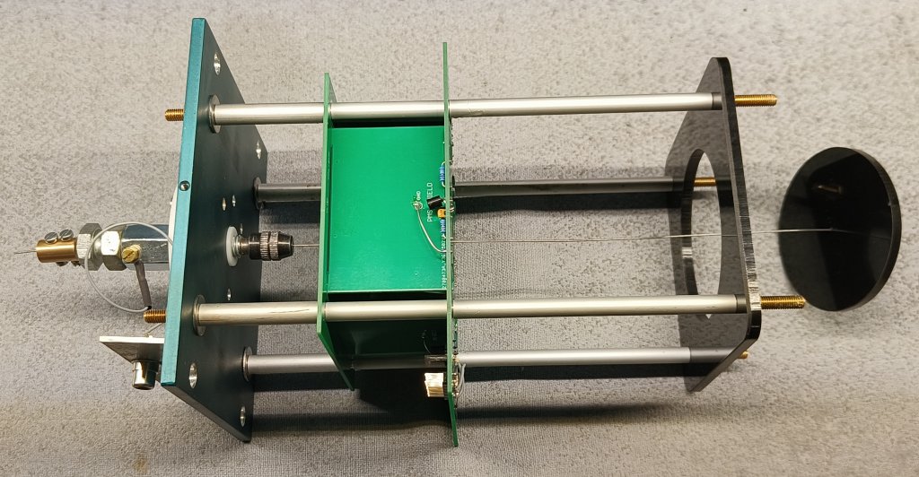
Fig 4. The complete Top Unit with Centering Plate and Disk. (click for larger)
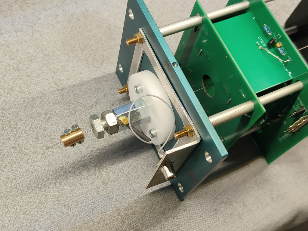
Fig 5. Detail of the top Unit. (click for larger)
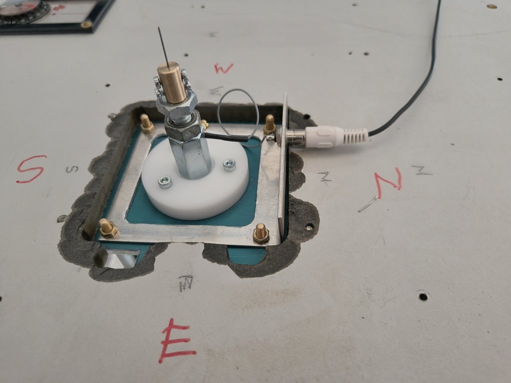
Fig 6. On Top of the Frame showing the electrical connection for the 465 kHz signal. (click for larger)