In brief:
The Q or quality factor of a pendulum (in genaral, a resonator) is the ratio of energy loss per radian of oscillation.
For a foucault pendulum we need to know the Q to estimate the parameters for the so called "Schumacher" drive method.
The Q also tells us how well the frequencies of the major and minor axis of the ellipse can be distinguished.
The first measuremnt of the Q was done on 2025-01-23, when the unit was stil on on a somewaht wobbly table. This may have an effect, we will repeat the measurement when the unit is on a more solid base.
The method I used was by manually launching the bob, logging the positions of the bob during the decay of the movement and later comparing the decay curve with an e-power function.
Before this experiment the position measurement system (PMS) had been tested and calibrated.
Also the detection of center passes was active. The amplitude measurement system with the Rim electrode was not yet active.
The bob was launched from ca 150 mm out of the center.
On the Dashboard program the checkbox Log_PMS was checked, which causes a log entry to be made for each message arriving from the PMS.
A line of this logfile contains: Status, PositionCounter, North, South, East, West, where Status tells us if a centerpass has been seen, and if we had a fisrt or a second HalfSwing. PositionCounter is not used in this experiment, and North, South, East, West are the raw A/D values from the PMS.
The log file was then processed by the program ReplayHallRaw, which does the following operations:
For each line from the log file the normalized positions were calculated as
PosNS:= (North - South) / (North + South);
and
PosEW:= (East - West) / (East + West);
Then the distance from the center was calculated as D:= sqrt ((sqr (PosNS) + sqr(PosEW)); and the farest and closest values were tracked.
The farest distances were taken as the amplitude of the major axis of the ellipse. The minor axis was ignored. The values for the major axis were averaged with a leaking bucket algorithm. When the Status reported (HalfSwing and SeenCenter) that is a whole pendulum period, the number of periods was increased, and at every 20st an entry in a new logfile was made, with the number of the period and the amplitude of the major axis scaled to some arbitrary value. This file was entered in a spreadsheet program and compared with a function ScaleY / e (N * ScaleX) These functions were plotted in a graph and by fiddling with ScaleX and ScaleY the curves were fitted together.
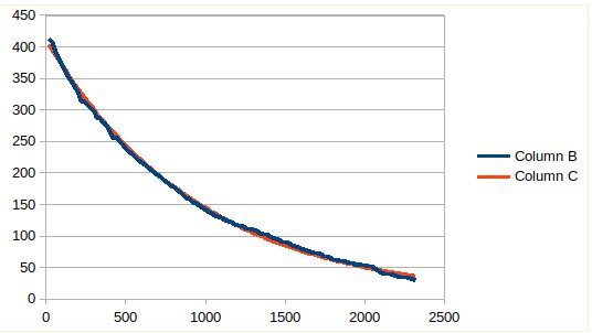
Fig 1. Measured decay (blue) and calculated e-power function (red)
We see that the decay follows a perfect e-power, which means that for this bob the air friction is a constant factor.
The 50% value is reached after 680 periods, which means a Q of 680 * 4.53 = 3080.
The 37% value is reached after 1000 periods, which gives a Q of 1000 * pi = 3140, well in accordance.
Conclusion: We have a Q of around 3100.
Calculations about the separation of the frequencies of the minor and major ellipse axis.
With the program SimDeltaF (*) I calculated the frequencies for a length L = 0.9 meter.
a/L= 0.0000000 Theta= 0.0000000, F= 0.525452400722815641, dF= 0.000000000000000000
a/L= 0.0500000 Theta= 0.0500209, F= 0.525370231346113805, dF= 0.000082169376701836
a/L= 0.1000000 Theta= 0.1001674, F= 0.525122909606541877, dF= 0.000329491116273764
a/L= 0.1500000 Theta= 0.1505683, F= 0.524707961643863688, dF= 0.000744439078951953
a/L= 0.2000000 Theta= 0.2013579, F= 0.524121151185604053, dF= 0.001331249537211588
For an amplitude of 150 mm we find a frequency difference of 0.74 10-3 Hz, at a center frequency of 0.52545 Hz
Then I made a pSpice simulation of two resonator circuits with these frequencies and a Q of 3100:
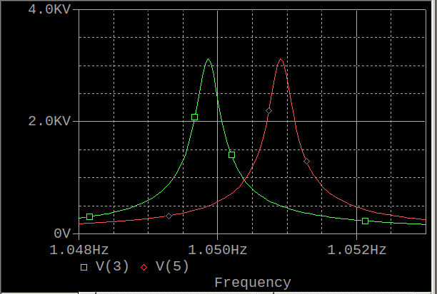
Fig 2. Spice simulation of resonators.
The input voltage was 1 volt, we see a upswing to 3100 Volts.
The frequencies of the major and minor axes differ more than the bandwidth of the resonators, so there is a chance that I am able to drive the pendulum with the frequency of the major axis, while not exciting the frequency of the minor axis.
Below the circuit definition of the two series resonators.
L and C were tuned to the desired frequencies, R was tuned for the desired Q.
Circuit to simulate major and minor axis resonance
* Voltage source
v1 1 0 AC 1
* Resonator major axis 0.525064 Hz
r1 1 2 0.00032
C1 2 3 0.303115
L1 3 0 0.303115
* Resonator minor axis 0.525452 Hz
r2 1 4 0.00032
C2 4 5 0.30289
L2 5 0 0.30289
* Simulation
.ac lin 500 0.524 0.526
.probe
(*) The program SimDeltaF uses the classical formula
for the period of the minor axis with amplitude > 0, and the formula
for the major axis wit amplitude a, where Theta = arctan (a / L)
Source: https://en.wikipedia.org/wiki/Pendulum_(mechanics)