The electronics part consist of several printed circuit boards,
- Arduino Shield (ASH) adapts the Arduino processor board, a Network interface board and a DDS (Direct Digital Sythesizer module to generate the 465 kHz signal for the wire.
- The Receiver Board (RCB) contains 6 almost identical small bandwidth receivers for the 465 kHz signals from the Position Measurement System PMS and the Center and Rim Pass detection.
- The bottom board of the PMS contains the high-impedance Pre Amplifiers to measure the signals from the sensing electrodes.
- Below the bottom plate of the frame sits a dual Pre-Amplifier board for the Center- and Rim pass signals.
- And of coarse we need some Power Supllies.
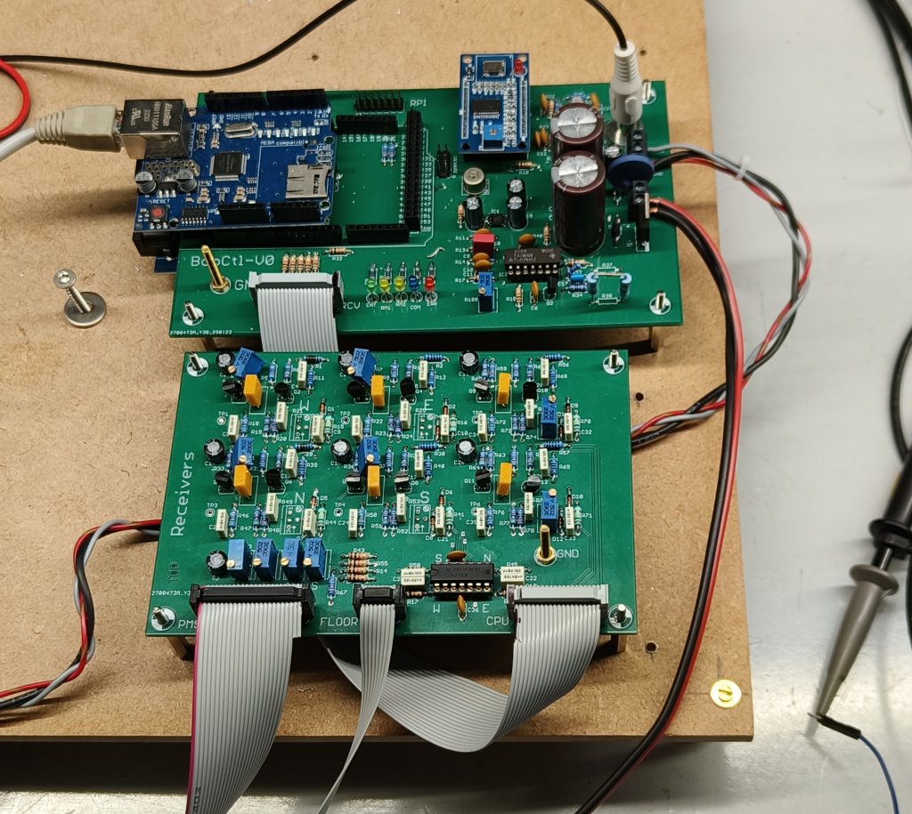
Fig 1. The Arduino Shield (top) and the receiver board.
Following the clock from 11:00:
- The Network interface module. Below it (not visible) sits the Arduino MEGA 2560 board.
- The DDS module produces the 465 kHz signal for the PMS. The DDS output frequency can be digitally adjusted in very small steps. After further division to approximately 1 Hz it will form the base for the drive timing in the experiment to excite the resonance frequency of the major axis of the ellipse.
- The RCA connector with the 465 kHz signal to the wire.
- +24V and +5V from the power supplies.
- Connection to the drve coil. The driving circuit is now a controlled current source.
- The receiver board has flat cable connections to the Arduino Shield,
- the floor unit pre amplifiers,
- and the PMS.
---- More to follow----