Overview of the Electronic Hardware. Latest change 2025-11-03
In brief:
The electronic circuitry in this kit consists of 7 different PCB's, 3 of which do not contain electronic components.
The basic Idea for measuring the actual position of the pendum is as follows:
- The pendulum wire carries a 465 kHz signal, which is picked up by 4 electrodes placed around the wire near the top.
- These signals are amplified and processed into the Position Information.
To keep the pendulum in motion there is a magnet on the lowest point of the bob and an electric coil in the center below the bob.
- The coil is driven with electrical pulses at exactly the right time. The magnetic field of the coil pushes the bob away from the center, without a preference for a certain direction.
In the center below the bob is a second coil in which a voltage is induced when the bob with its magnet flies over.
This voltge is used to trigger the Drive timing.
In an optional coil with a radius of ca. 2/3 of the pendulum amplitude (RimCoil) also a voltage is induced. This voltage can be used to measure the pendum amplitude.
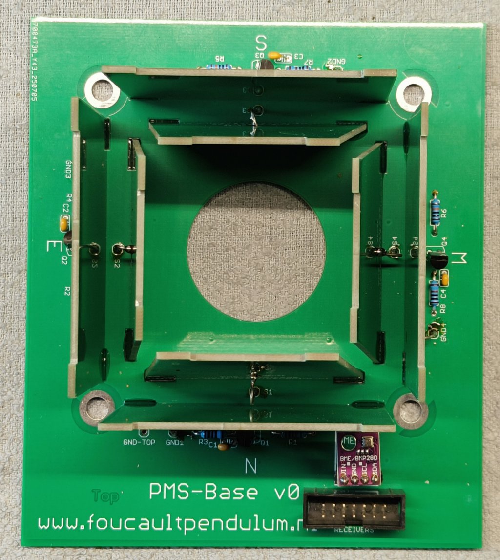
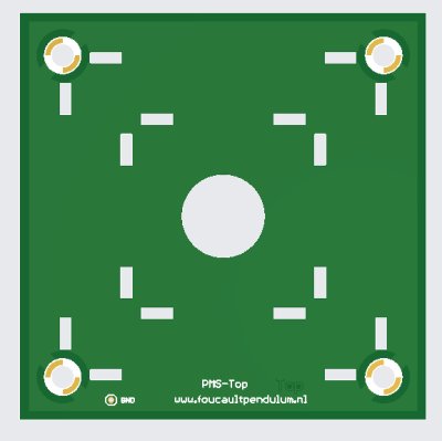
Fig 1 The electrodes of the Position Measurement System seen on top. Fig 2. Top Cover
We see the four sensing electrodes surrounded by the 4 shielding electrodes.
On the base plate we have the 4 pre-amplifiers, and in the lower right a climate sensor.
The pendulum's wire with the 465 kHz signal is to go through the center. The electrodes will pickup that signal with a strength depending on the distance between te wire and the electrode.
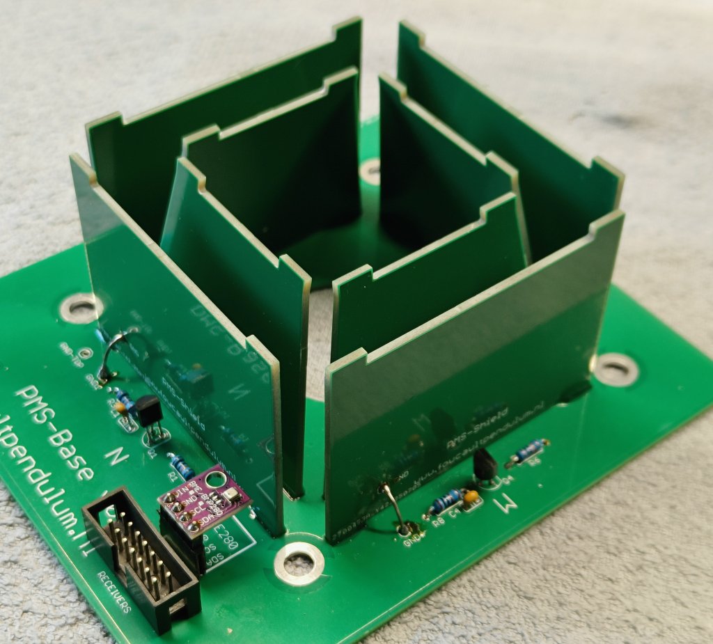
Fig 3. The PMS in side view.
The top cover of fig 2 provides more complete electro-magnetic shielding and provides more rigidity.
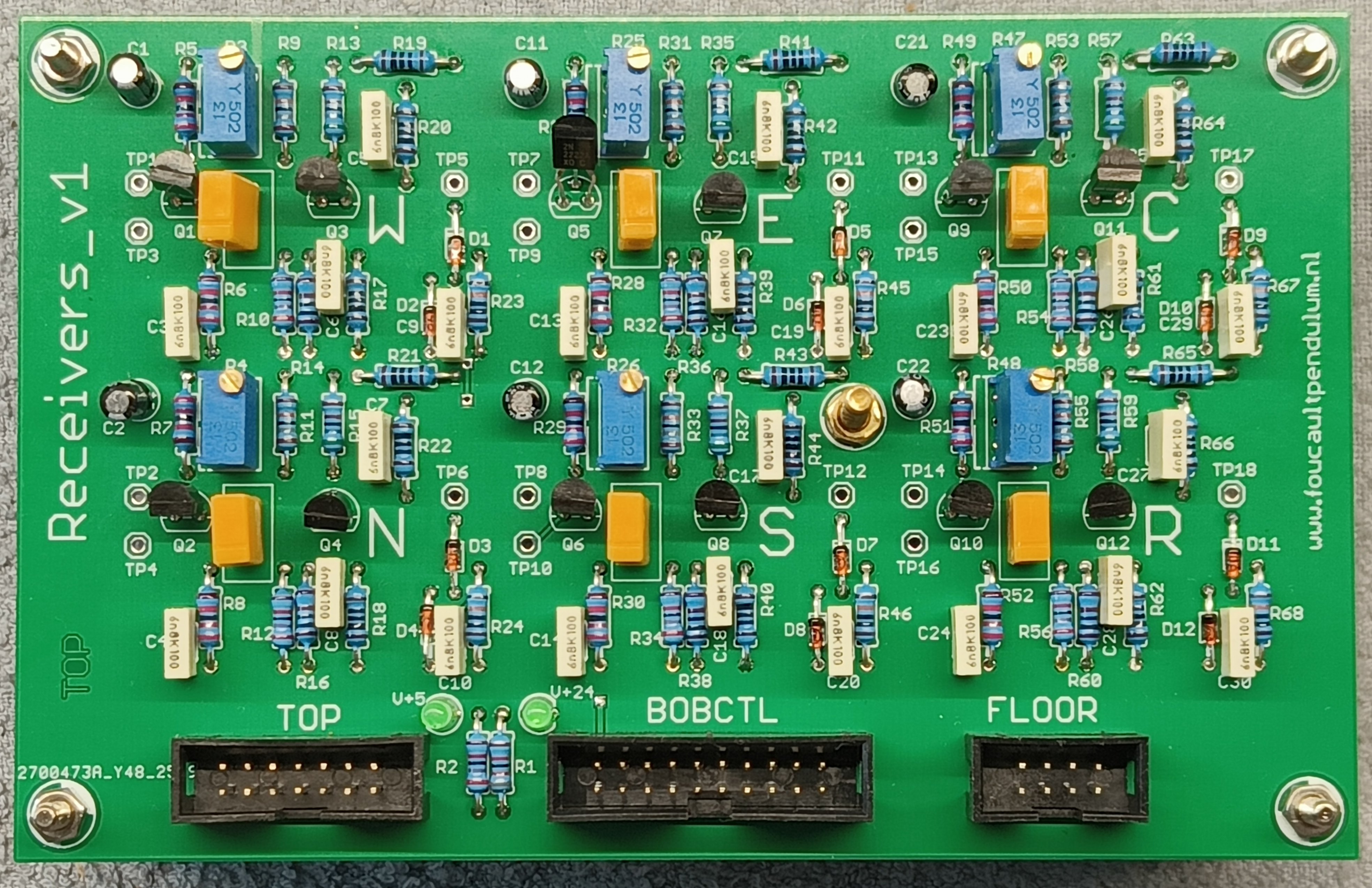
Fig4. The Receiver board.
This board contains 6 identical receiver circuits with a bandwidth of a few kHz around the frequency of 465 kHz, together with an amplitude detection circuit. 4 receivers process the North, South, East, West signals from the PMS, the other 2 the signals form capacitive Center and/or Rim electrodes.

Fig 1.The BobControl PCB. (click for larger)
This board forms the basis of the whole system.
The controller with the firmware is on an Arduino MEGA 2560 below the board (partly visible on the photo).
It communicates with a PC or laptop by Ethernet using the piggybacked ETH interface shield, left away on this photo.
Other functions are: generating the 465 kH signal and driving the pendulum wire with it, generating the Drive Pulses to keep the pendulum moving, sensing Center- and RimCoil Passes of the bob and processing the signals from the Position Measuring System.
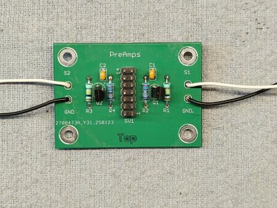
Fig 6. The Pre-Amplifier board.
This board is required when one wants to use the Capacitive Center Pass detection and/or the Capacitive Rim detection method.
It contans two pre-amplifiers identical to those on the PMS Base board. and should be placed below the bottom (coil) plane of the pendulum and be connected to capacitive Center Pass and/or Rim electrodes.